By Jay Spivack, W7PJS, ![]()
Posted here with permission of Ray Osterwald at Electric Radio Magazine--article appears in ER #259
The GPT- 750 B-2 is, in my opinion, one of the finest A.M. Transmitters ever built. It was built to provide 1000 Watts CW or 750 Watts A.M. output in Continuous Commercial Service from slightly above 1900 kHz to 32 MHz. It will LOAF at maximum legal amateur PEP. The 750 is extremely reliable, but after 50 years, the Master Oscillators of these transmitters often need service or repair. There is very little, if any, information in the TMC manuals about the servicing of these Master Oscillators.
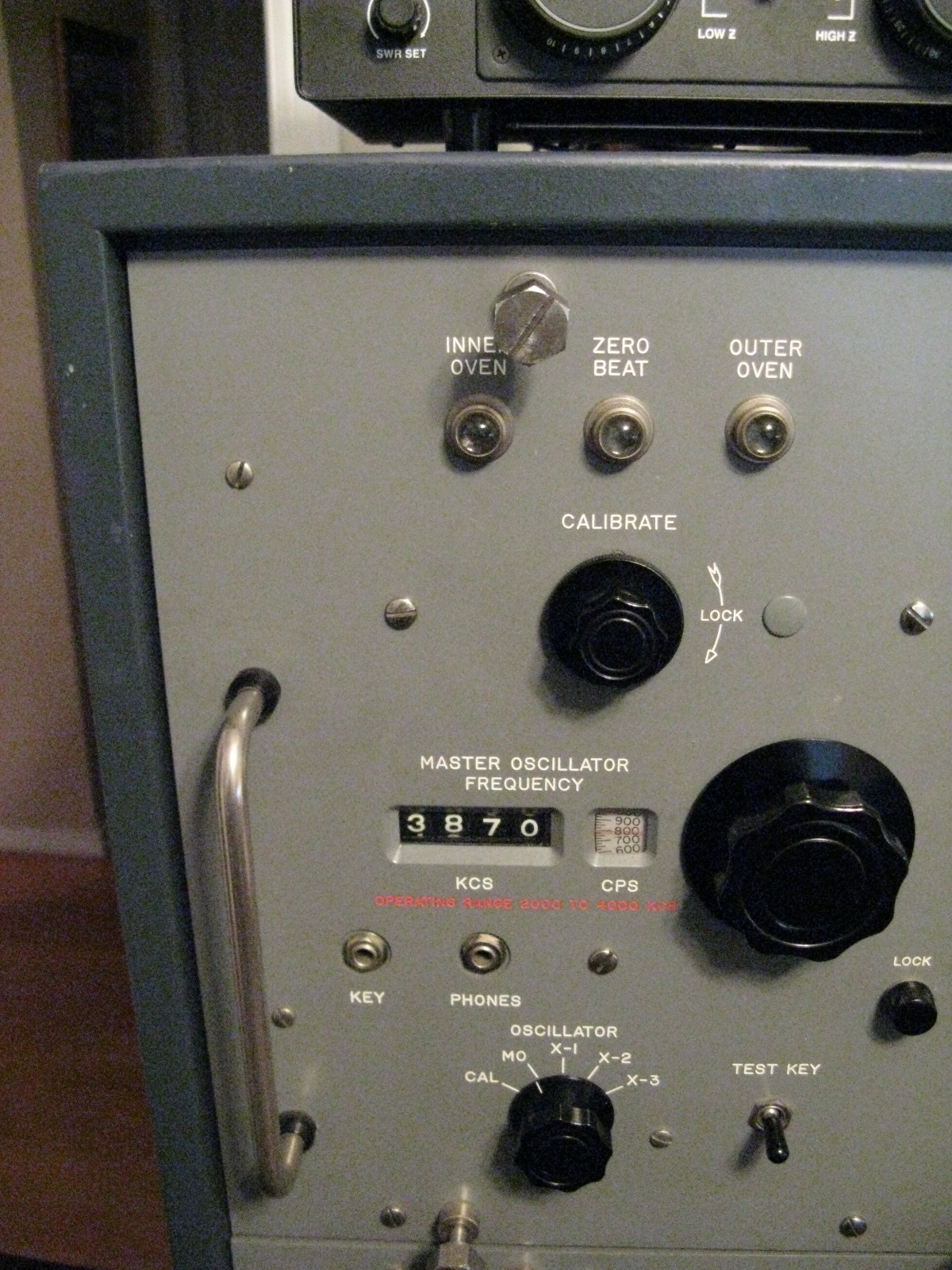
Figure 1: Master Oscillator as seen from the front panel of transmitter.
This article is a detailed discussion of how to repair the “Matruschka like” Master Oscillator.
The following are the tools and equipment recommended for the work to be done:
Vanco K -38 screw holding slotted screwdriver, 8 inch shank
Slim long shank slotted screwdriver, 10 inch shank. Diameter of shank 3/16 inches or less with 1/4 inch blade.
Power supply capable of 120 – 130 V DC at 20 MA. And 6.3 VAC at 2 A.
A Frequency counter
DeoxIT D5 cleaner in spray can.
Lithium grease.
WD-40
Capacitor Bridge with 5% accuracy or better.
Digital camera to document each step of disassembly to ensure proper reassembly.
Repairing the Master Oscillator is not rocket science. I would recommend that you document each step of the disassembly to facilitate reassembly without missteps. The digital camera will allow this documentation. Prior to removal of wires from the four terminal strips on the Interconnect Chassis, I suggest that you draw a simple pictorial diagram, which will enable the re-installation of the proper wire to the proper terminal.
It is probably best to remove the top draw (RTF) from the transmitter and place it securely on a workbench to facilitate access to the MO. As this is a heavy drawer, it is suggested that two people accomplish this.
(1) Remove the Interconnect Chassis. To do this, remove the coupling collar on the shaft of the oscillator selector, then the four nuts, bolts and washers holding the chassis in place.
(2) Remove four screws from rear tube cover. Remove tube cover and insulating material and tape the four screws to the tube cover.
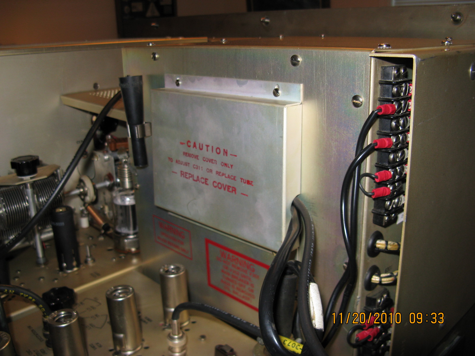
Figure 2: Rear of MO, showing the tube cover installed.
(3) Remove the ten screws from the rear plate of the M.O. Remove the rear plate and tape the ten screws to it.
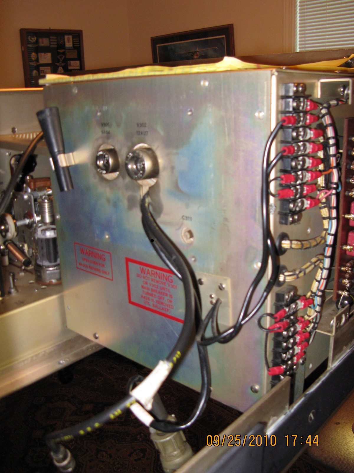
Figure 3: Rear-outside Cover of MO
(4) Remove the white insulation pad and keep it with the plate and screws in step 3.
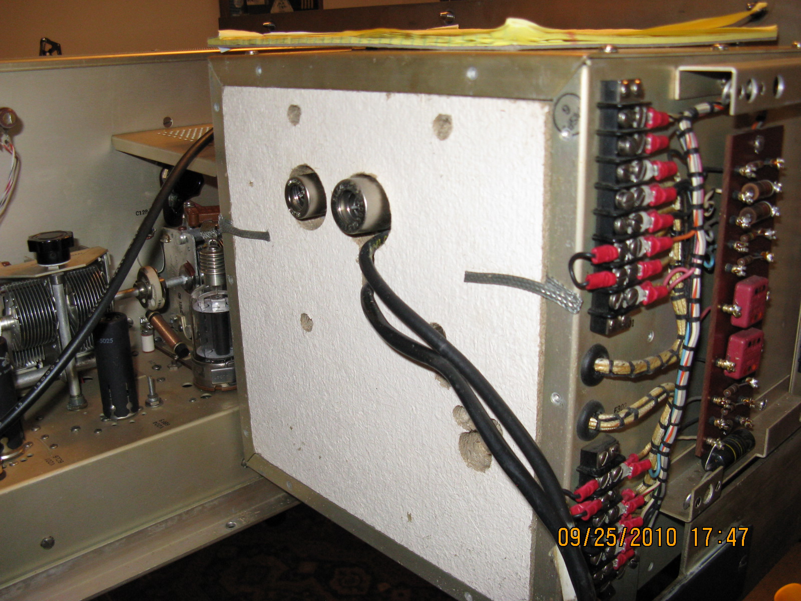
Figure 4: Rear cover has been removed, showing first insulated pad of outer oven.
(5) Unscrew the eight screws and washers, and remove plate, and white insulating material.
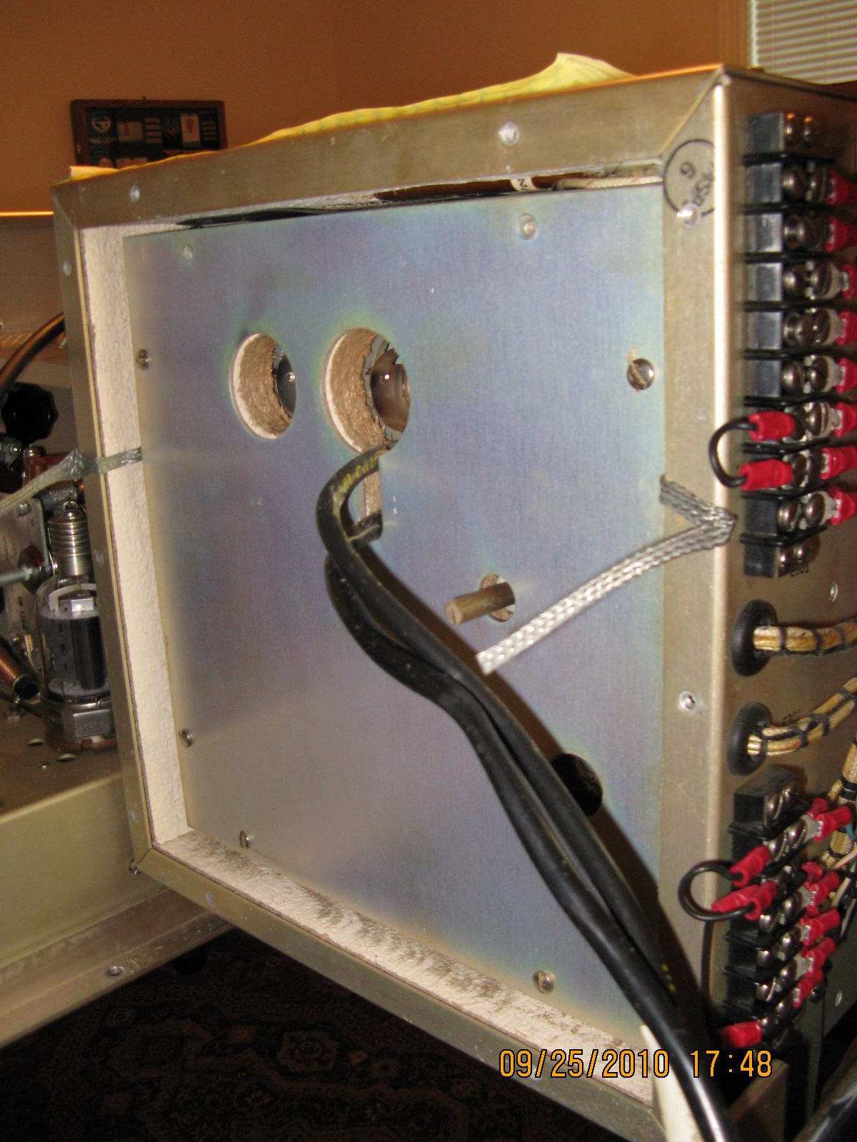
Figure 5: The second cover is exposed.
(6) Unscrew the six screws and washers and remove the plate exposing the M.O. in the cast aluminum housing.
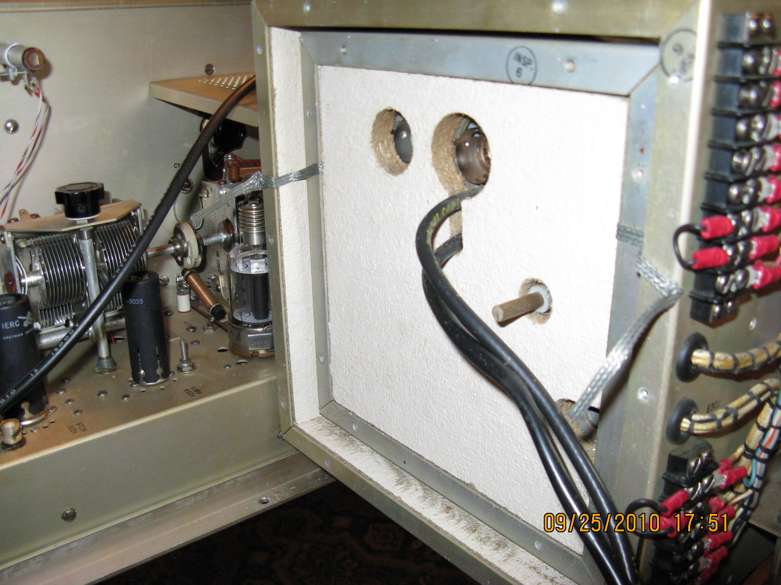
Figure 6: Insulating pad, Inner Oven.
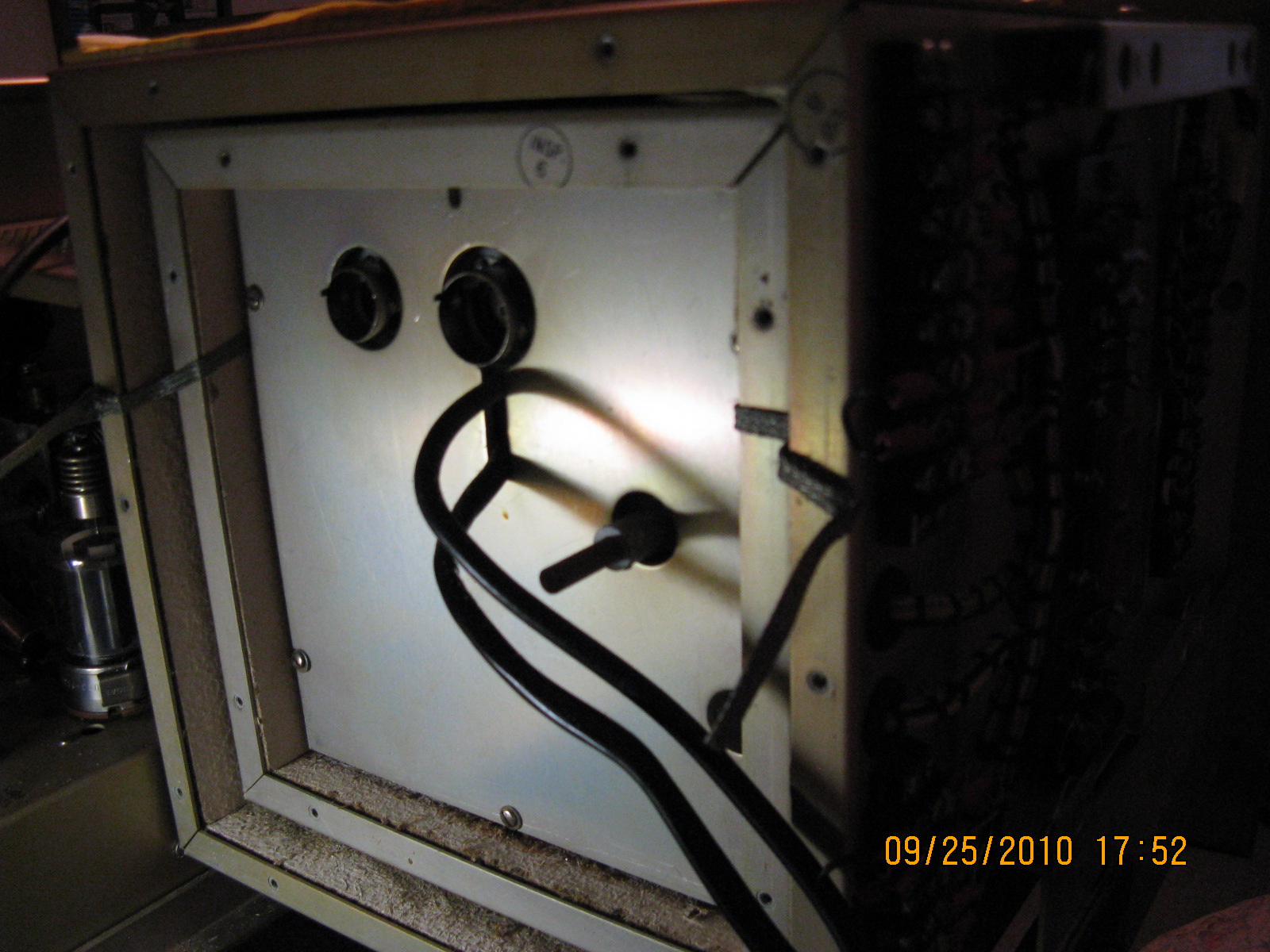
Figure 7: Back cover of cast aluminum case.
(7) At this point, be sure to adjust the M.O. Frequency on the front panel of the R.F. Deck to 1900KHZ. Note: The Cardwell Capacitor C-301 should be fully meshed.
(8) Remove the two Allen screws (nearest the M.O.) from each the three flexible couplers connected to the shafts of C-301, C-303, and L 301. C-301 is the M.O. main tuning. C-303 is the calibration capacitor accessible behind the snap button near the written word “calibrate” on the front panel. and L- 301 is the Calibrate control on the front panel. Carefully put these Allen screws aside.
(9) Now remove the M.O. in the cast aluminum case by unscrewing the four large screws which are holding the cast aluminum case in place. You may need a flashlight to locate these screws. Use the slim long shank screwdriver and the Vanco screw holding screwdriver to remove these screws.
(10) Next remove the four screws holding the M.O. in the cast aluminum case.
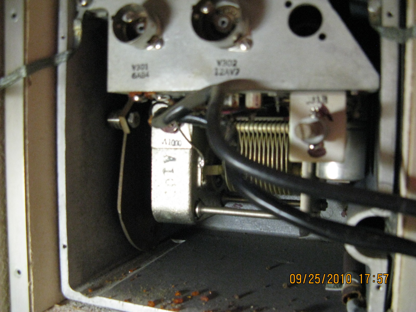
Figure 8: Rear of Master Oscillator inside cast aluminum case.
The next step is to clean, inspect and lubricate the gears, cam roller and shaft bearings. Then carefully and thoroughly clean the rotor contacts on the Cardwell capacitor with DeoxIT D5. In many cases this is the problem with the M.O. Next, clean the rotor contacts of C-302. This is the frequency adjust capacitor that is connected to the roller that rides on the elliptical cam. Use DeoxIT D5 and clean the rotor wiper contacts thoroughly.
At this point, using the Capacitor Bridge, ensure that fixed capacitors C- 304, C-305, C-306, and C-319 are all within the 5% tolerance range. Be sure that there isn’t any corrosion on the base pins of the tubes V301 and V302. With a flashlight ensure that the corresponding tube sockets are free of corrosion or clean or replace, if necessary. Check that the two RG-58 coax cables are supple and in good condition, or replace.
Next, test the M.O. by connecting a power supply to the 6.3 VAC filaments at C-323, as well as 120 VDC to the plate circuit of V-301 at C-321. Be sure to provide a ground return at the bottom of L302 and R-302. Connect the frequency counter. Tune a receiver to between 1900 and 2000 kHz. The M.O. should be oscillating. You should be reading the frequency of the M.O. on the counter and with the receiver set to the CW mode you should hear a clean tone, assuming a ripple free power supply. Tune the M.O.; while doing so, the receiver should not detect any intermittent output of the M.O. and the frequency should be very stable and not jump erratically as the tuning capacitor is smoothly tuned. If necessary re-clean the rotor contacts.
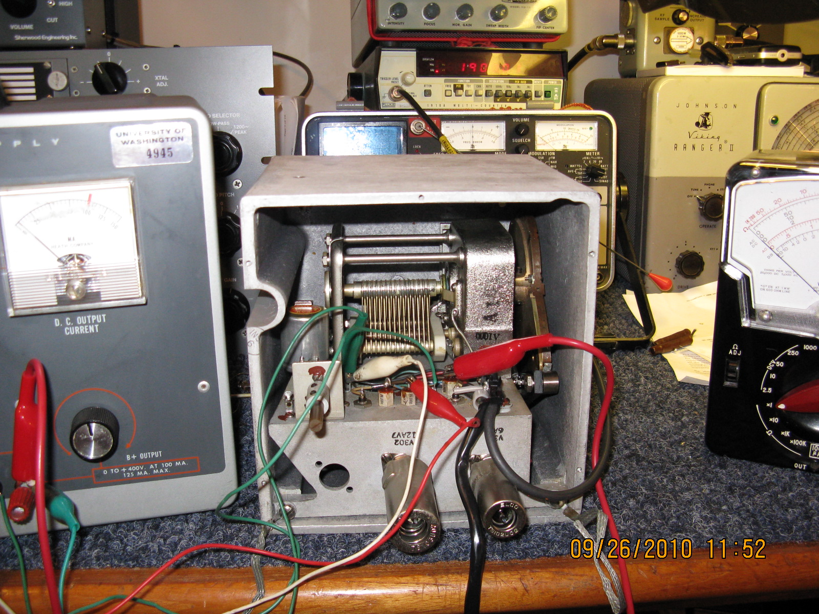
Figure 9: Testing the master oscillator, inside of cast aluminum case.
With C-303 half meshed, and L-301 in the center of its range, the output of the M.O. should be tunable with the Cardwell Capacitor from at least 2000KHZ to 4000KHZ. With The Cardwell fully meshed, the output of the M.O. should be approximately 1900 KHZ. Test the M.O. by disconnecting and reconnecting the B+ to ensure the oscillator restarts each time. Check the M.O. for mechanical stability (gently).
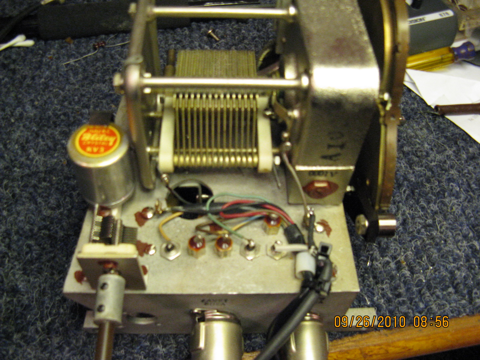
Figure 10: Rear of MO, out of cast aluminum case.
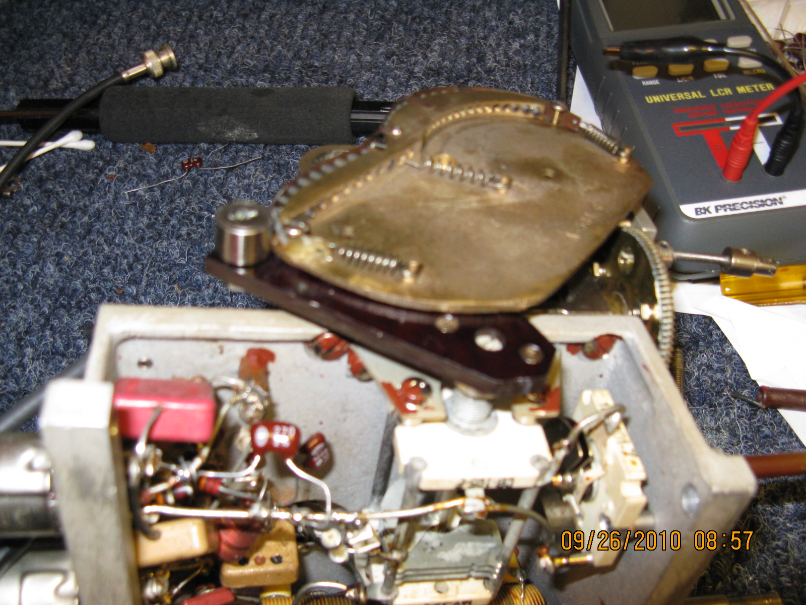
Figure 11: Partial bottom view of the MO, showing the freq. adj. capacitor and its roller and elliptical cam.
Replace the M.O. in the Cast aluminum case, when you are satisfied with the previous tests, and re-secure with the four screws.
I suggest that all previous tests are repeated while the M.O. is now in the cast aluminum case, before reassembly in the inner oven.
Important NOTE: When satisfied that the M.O. is working properly be sure that the Cardwell capacitor is fully meshed. Use the straight edge of a ruler to ensure this. Now, carefully reinstall the cast aluminum case (containing the M.O.) by replacing the four screws with washers, using the Vanco screw holding screwdriver. This is often a two man operation as you simultaneously must carefully align the three shafts in the flexible couplings before screwing in the four screws and washers. Be sure that you do not over tighten these four screws as they are threaded in a fiber washer. Reinstall the six Allen screws in the couplings, and tighten. One of the Allen screws in the shaft of the main M.O. tuning should be tightened on the flat surface of the flexible shaft of the Cardwell capacitor to prevent the shaft from turning as the main tuning knob is spun. It is important that the position of the shaft of the Cardwell main tuning capacitor was not disturbed in this process.
After the four screws and washers are carefully secured, without over tightening, I would suggest that the M.O. is retested using the test power supply, counter and receiver. Now would be an excellent time to ensure that the M.O. tunes from at least 2000KHZ to 4000KHZ. You can also do a preliminary calibration per the GPT-750 manual. If everything looks good, discontinue the testing, and begin the reassembly by referring to your digital pictures, wiring notes and pictorial drawing.
Reinstall the Interconnect Chassis. Replace the R.F. deck in the transmitter and reconnect all cables and connectors.
The following test, calibration and procedure is to be performed with extreme caution and only by an experienced technician as there are potentially lethal voltages on this R.F. Deck.
To test the M.O. and to perform a calibration procedure on the M.O., connect the M.O. to the frequency counter. With the R.F deck open, pull out on the interlock shaft to defeat the interlock. Ensure that the Final Plate switch is in the off position and remains off through this entire procedure. Turn on the Main power switch. With the transmitter keyed but the Final plate switch off, (after the one minute time delay), the M.O. should be oscillating and the counter will be reading the output of the M.O. which will approximate the M.O. dial reading. Perform the M.O. calibration per the GPT-750 manual.
A word of caution: When turning the M.O. tuning knob always turn the knob slowly when tuning below 2000KHZ to prevent running the roller off the cam which could cause mechanical damage.
The following are the most likely causes of the M.O. to fail or not operate:
(1) Defective V301, or no contact between tube pins and tube socket due corrosion.
(2) Defective 4HTF4 filament ballast tube in the Interconnect Chassis. (you can temporarily bypass this tube)
(3) No filament voltage or B+ voltage. No ground return in V301 cathode circuit.
(4) Bad contact or no contact on the rotor of C-301, the main tuning capacitor.
(5) The possibility that the Master Oscillator tuning knob was rotated beyond the range of 1900khz to 4000khz causing the roller on the frequency adjusting capacitor to run off the cam. ( Caution: do not tune below 1900khz or above 4000khz on the main tuning knob).
One can see that the repair of the GPT-750 is not difficult. It is somewhat time consuming and admittedly a bit tedious. That said, it should give the owner of a GPT-750 transmitter immense satisfaction to accomplish this repair.
I would like to acknowledge the help and kindness extended By Tony Faiola, formally of TMC. Were it not for his encouragement and the information that he provided, I would not have attempted this project.
73 de W7PJS